Solvent Delivery System for Flow Chemistry Applications
A low-cost 3D-printed syringe pump capable of delivering at flow rates between 250-1000 µL/min.
My role
This was my 3rd-year dissertation project for ES327 Individual Project module.
Problem
Flow chemistry is an emerging branch of chemistry research and production processes, providing an alternative approach to traditional batch processes. This provides several advantages such as continuous and on-demand production, potential for automation and greater control of the reaction conditions. Many applications benefit from these including pharmaceutical production and testing, research and performing chemistry in space.
However, flow chemistry demands more specialised and traditionally expensive laboratory equipment. This presents limitations on the use of flow chemistry due to cost-effectiveness in some scenarios such as for small-scale research, smaller businesses or start-ups. Commerical syringe pumps cost ain the region of £2k each with actuator valves costing around £1.5k each.
The aim of this project is to design and build a prototype for a solvent delivery system which has reasonable accuracy and precision, with a focus on modularity and ease of manufacture.
Constraints
This project was for my 3rd year project module (ES327 Individual Project module). It spanned a total of 164 days but ran concurrently with other study and course deadlines.
The total budget for the whole project was £200.
The device was aimed to target selected flow rates between 250 µL/min and 1000 µL/min, typical flow rates that might be used in conjunction with other microfludic equipment. A reasonable accuracy of ±3% and outlet pressure ≥1 MPa were desired.
The prototype will only be tested with water, reducing the H&S risk of using dangerous solvents during testing.
Design & Decisions
There were many potential areas of focus when initially considering the design. I decided to focus primarily on accuracy, modularity, and cost as well as ensuring design manufacture and ease of use. This was to ensure maximum utilisation of the time and money available whilst producing a meaningful prototype as the project outcome.
Various pumping methods were considered including direct electromechanical, gravity-based and pneumatic/vacuum systems. Ultimately, the chosen concept uses a stepper motor and linear motion system to push/pull an existing syringe as this was determined to be the most feasible design by a weighted Pugh matrix.
The use of a pre-existing syringe presents benefits for chemical compatibility and also allows different syringes to be used, allowing the system to be taylored to different applications.
Iterative design is used to design the components, using rapid prototyping via 3D printing to evaluate each iteration.
Build
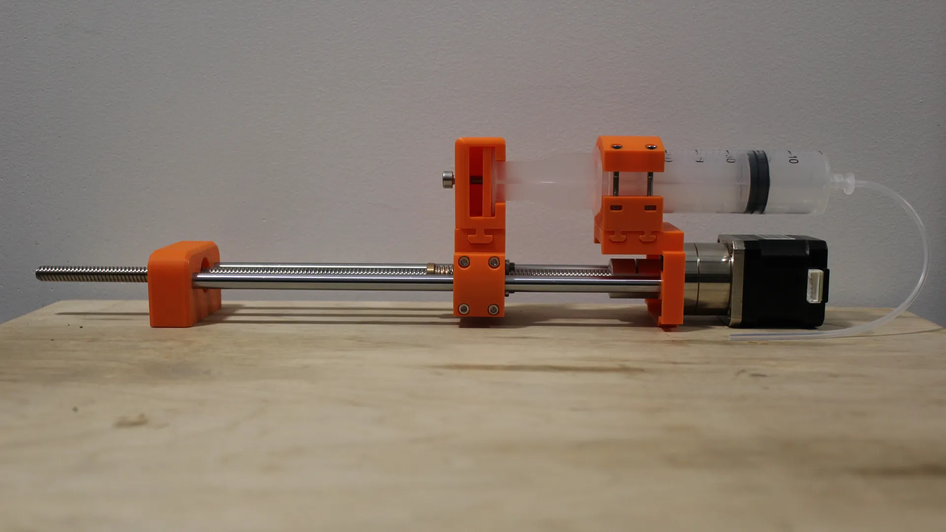
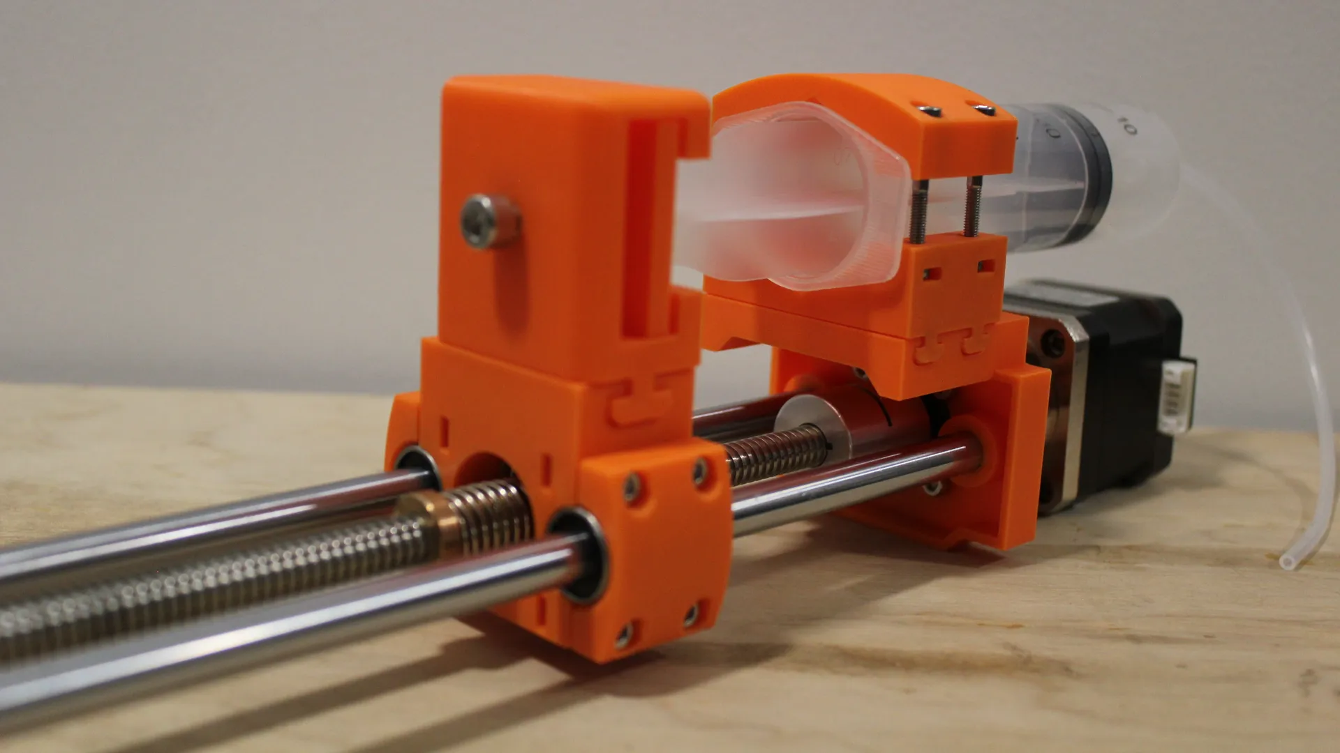
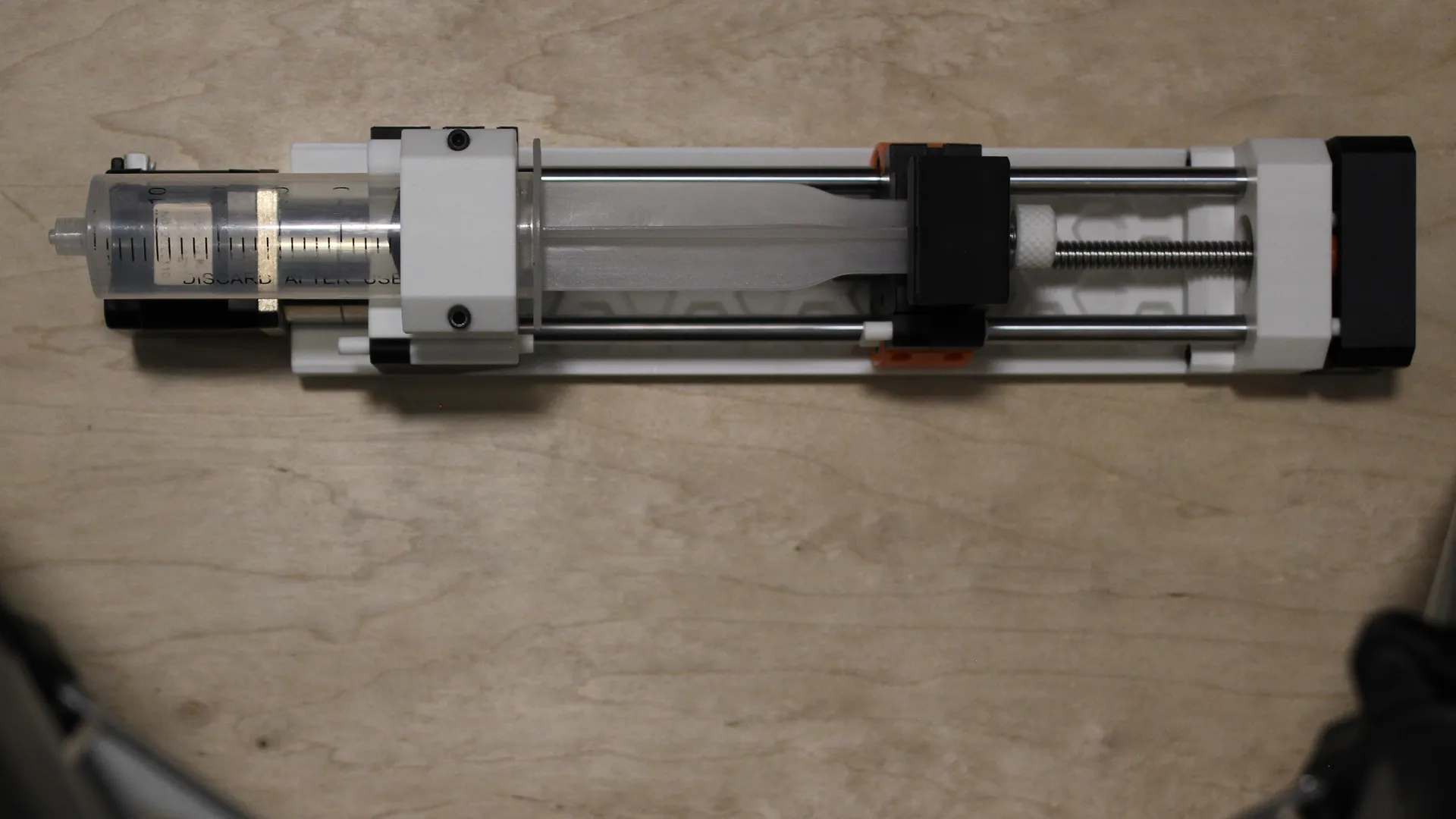
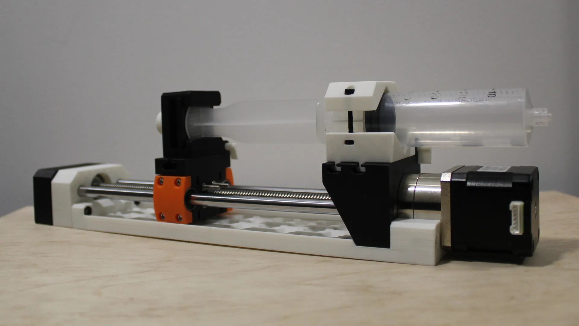
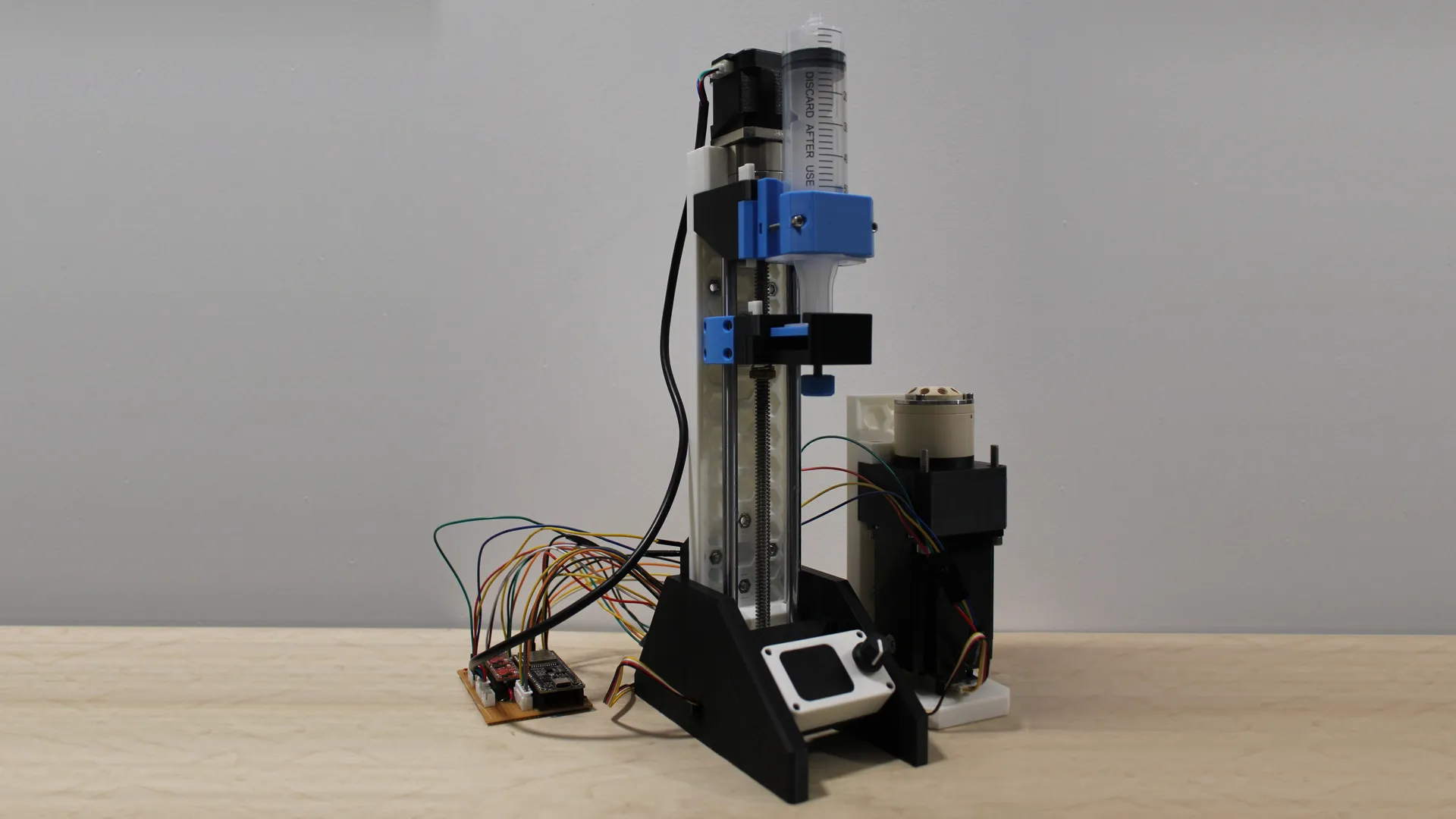
For the motor, a high torque NEMA17 stepper motor with 5.18:1 reduction gearbox is used to achieve the fine resolution required when paired with a 8mm diameter 2mm lead leadscrew and 60mL syringe. An anti-backlack nut is used to reduce backlash from the use of the leadscrew.
Calculations using fluid dynamics estimated an outlet gauge pressure of 2.46 MPa with this configuration.
The design evolved through different iterations using CAD (Fusion360) to create the design and the rapid prototypes as seen in the images.
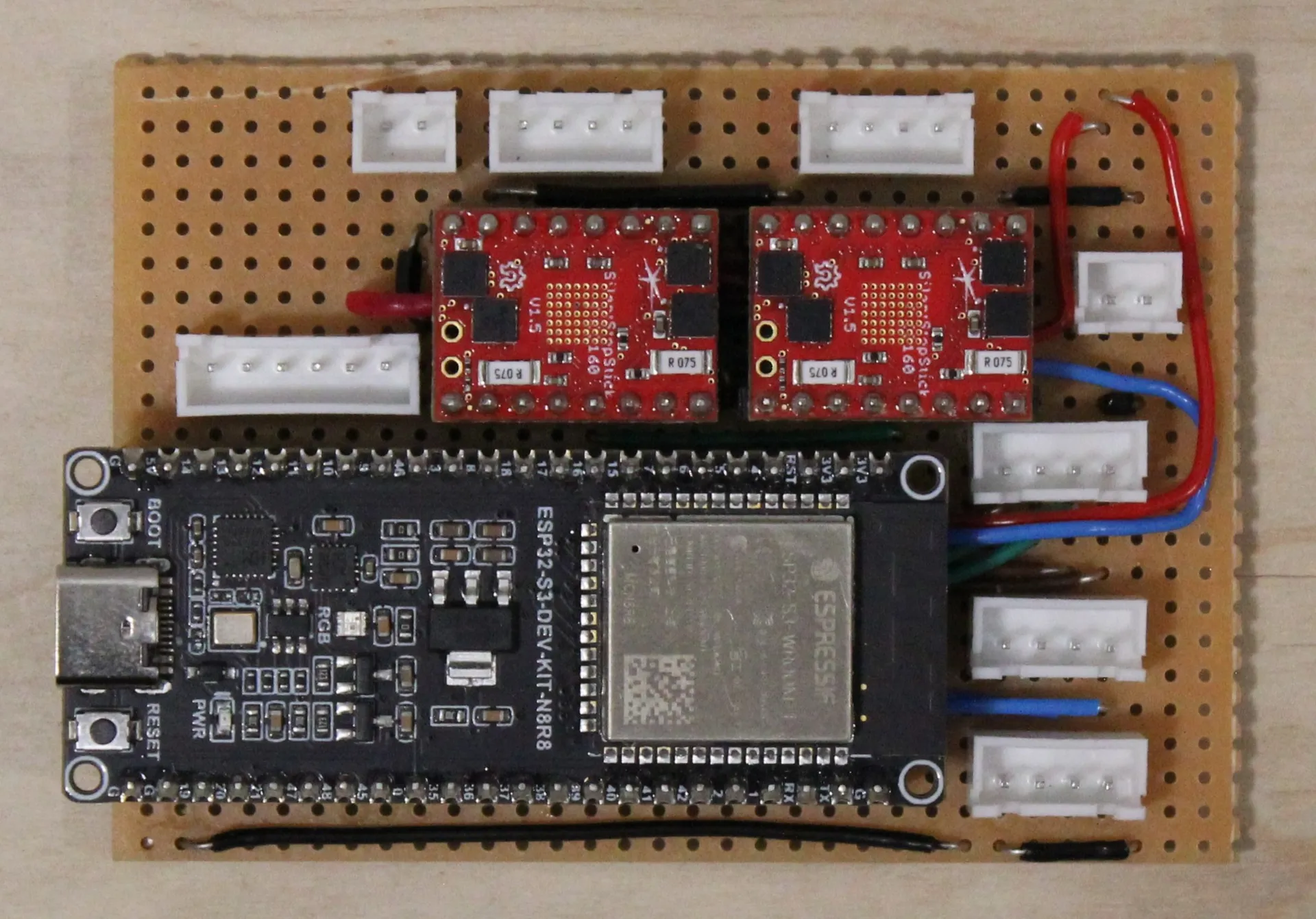
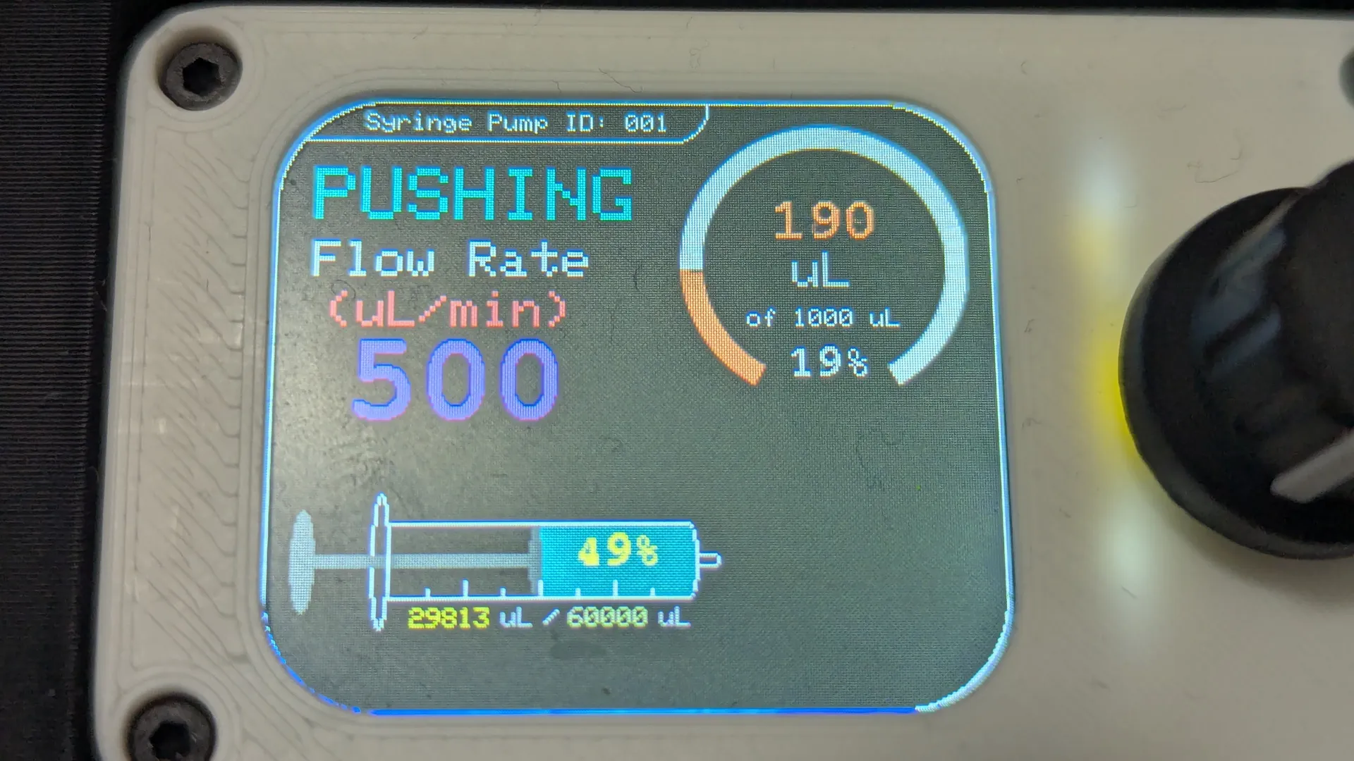
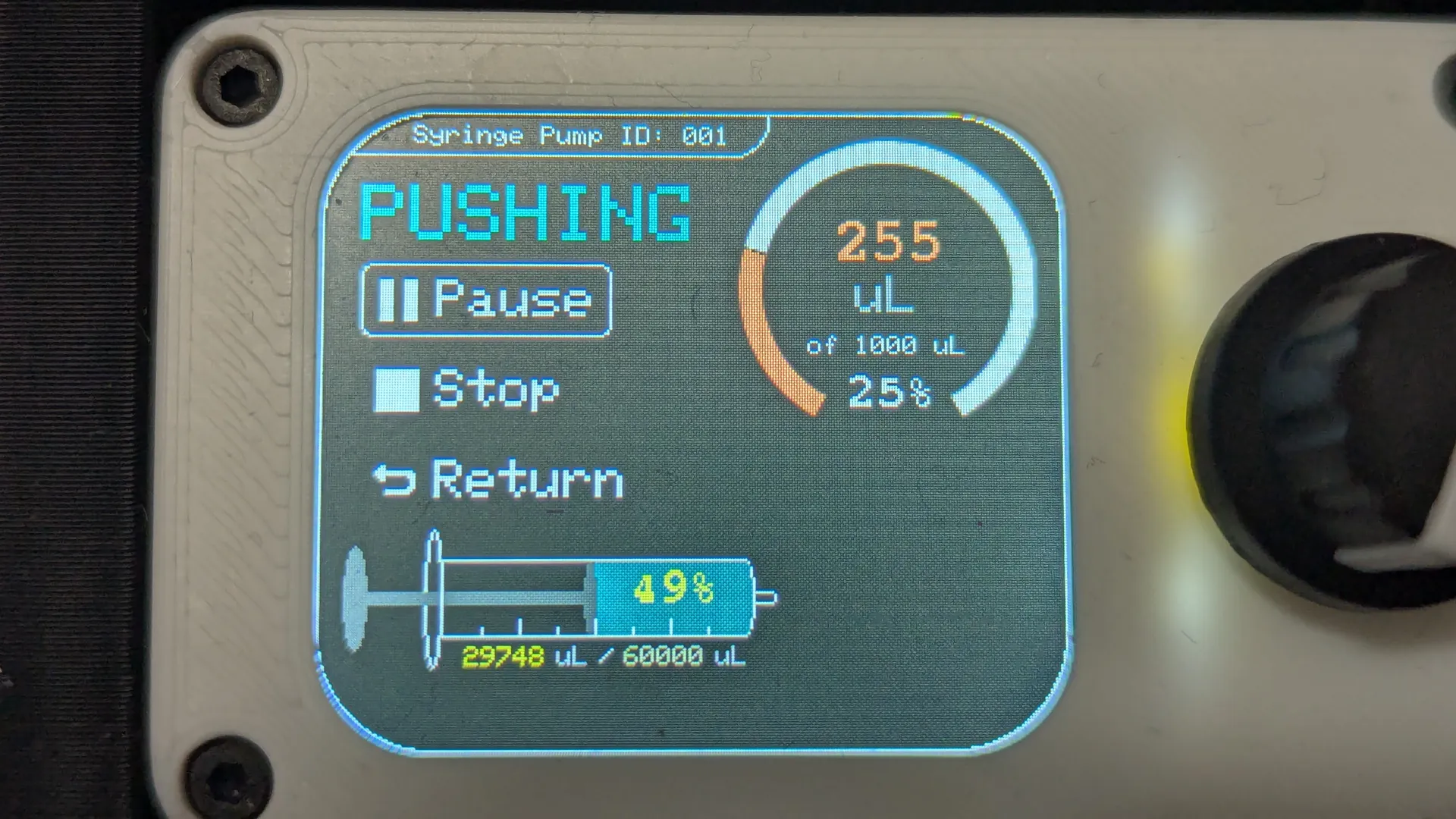
The control electronics use an ESP32-S3 microcontroller and dual TMC5160 motor driver chips: one drives the stepper motor for the pump, the other drives a NEMA23 motor which turns a microfluidic valve. A display and rotary encoder provides and easy to use interface whilst USB serial can be used for advanced control and automation. An AS5600 magnetic encoder is used to measure the leadscrew rotation and can therefore be used for closed-loop control.
Testing & Results
The prototype was tested in a lab using water dispensed though a tube into a beaker placed onto an analytical balance. This was non-ideal as ideally a flow rate meter would be used to measure the flow rate directly, however this equipment wasn’t available to me.
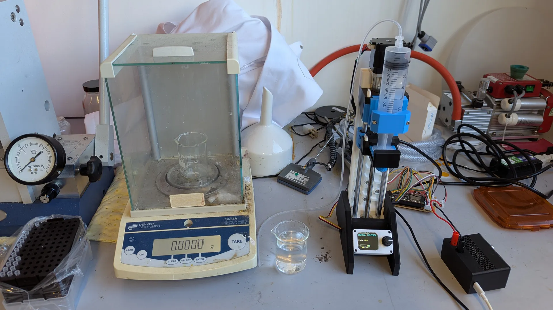
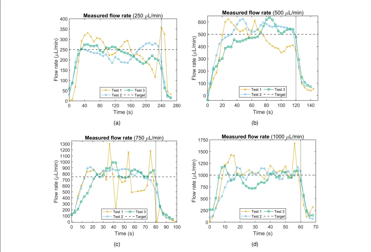
Despite this, results were promising. Accuracy ranged from 2.06% to 6.05% in the tests however, the precision was only moderate ranging from 13.3% to 20.1%. The likely largest source of error is the experimental method itself such as vibrations/movement of the tubing affecting results and the use of an analytical balance instead of equipment specialised for measuring small flow rates. There is also the potential of friction and backlash which could introduce error in addition.
Reflection and Future Improvements
Although the results are not quite as originally desired, the prototype is definitely a step in the correct direction especially given the time and budget constraints. The design considers design for manufacture and consists of entirely 3D-printed and off-the-shelf parts making it easy to replicate.
With additional time and budget, I would test the prototype in a more reliable way and consider inherently better technologies for some parts of the design. For instance, a ball-screw would present less backlash than the leadscrew and the stepper motor could be driven with FOC (Field Oriented Control). I would also explore the control side more, for instance integrating a flow sensor into the design would allow for closed-loop control of the whole pump and in turn likely increase accuracy and precision greatly.