Railway Cable Trough Inspection Robot
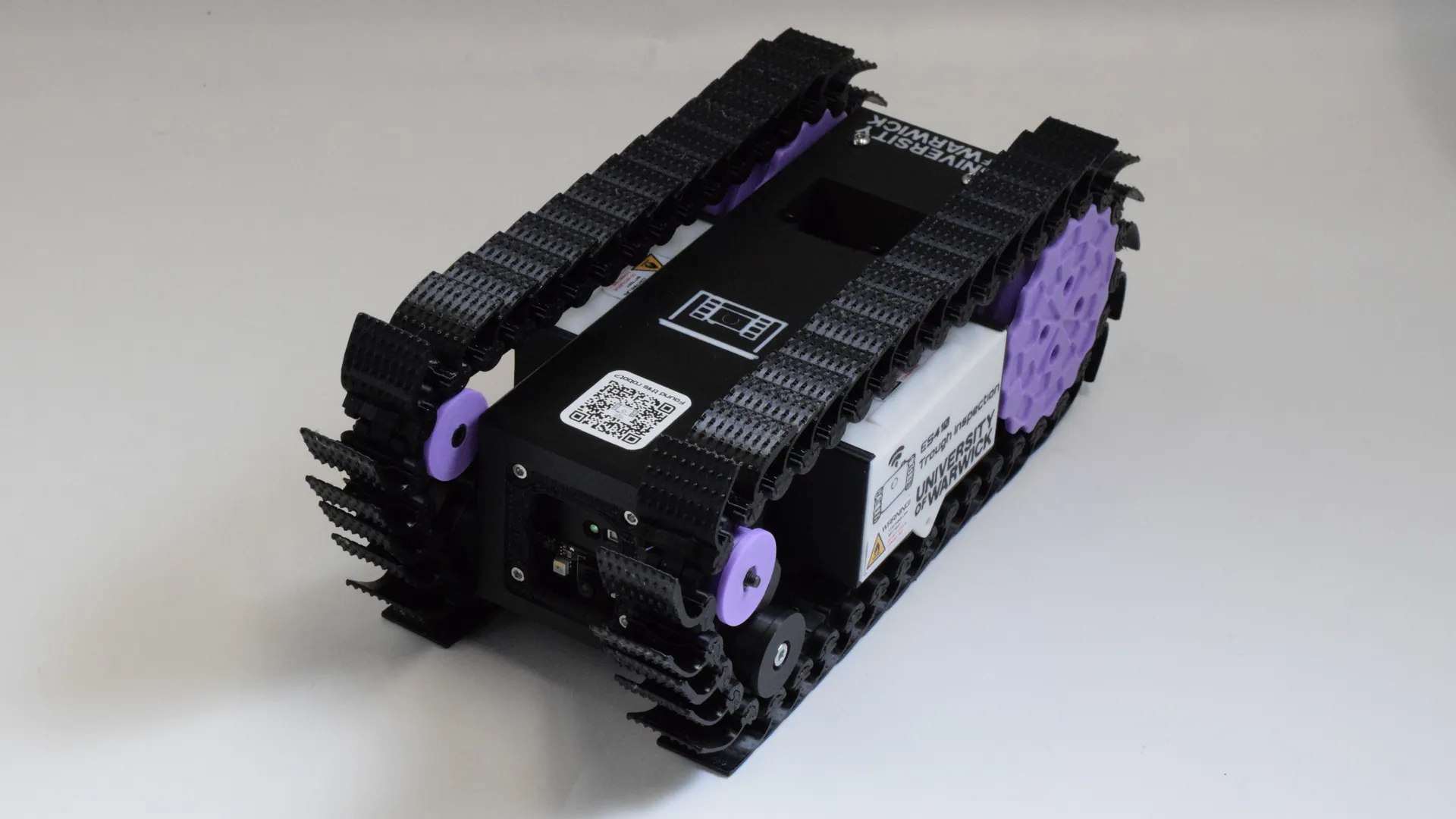
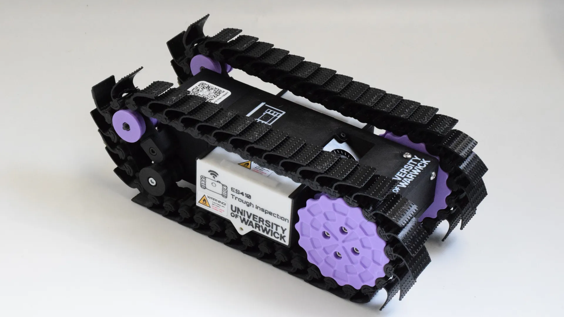
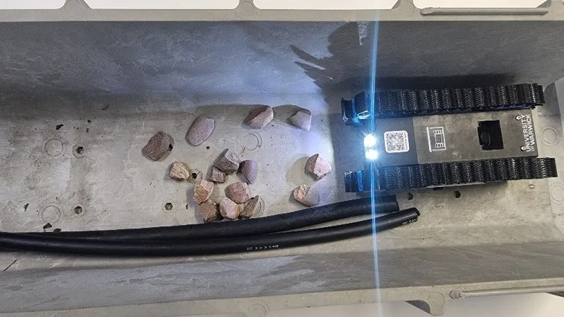
A prototype for a robot capable of remote and automated inspection of cable trough condition.
My role
Leader of the Electrical Sub-Team, managing group of three people. My personal responsibilities were selection of electronic and electromechanical components, creating the schematic and PCB layout, assembling the PCBs, developing firmware as well as managing the sub-team and delivering progress reports in meetings.
I also contributed to ideation and concept selection, testing and analysis, the creation of a marketing video, writing of a project report and preparation and delivery of a presentation and live demonstration.
Problem
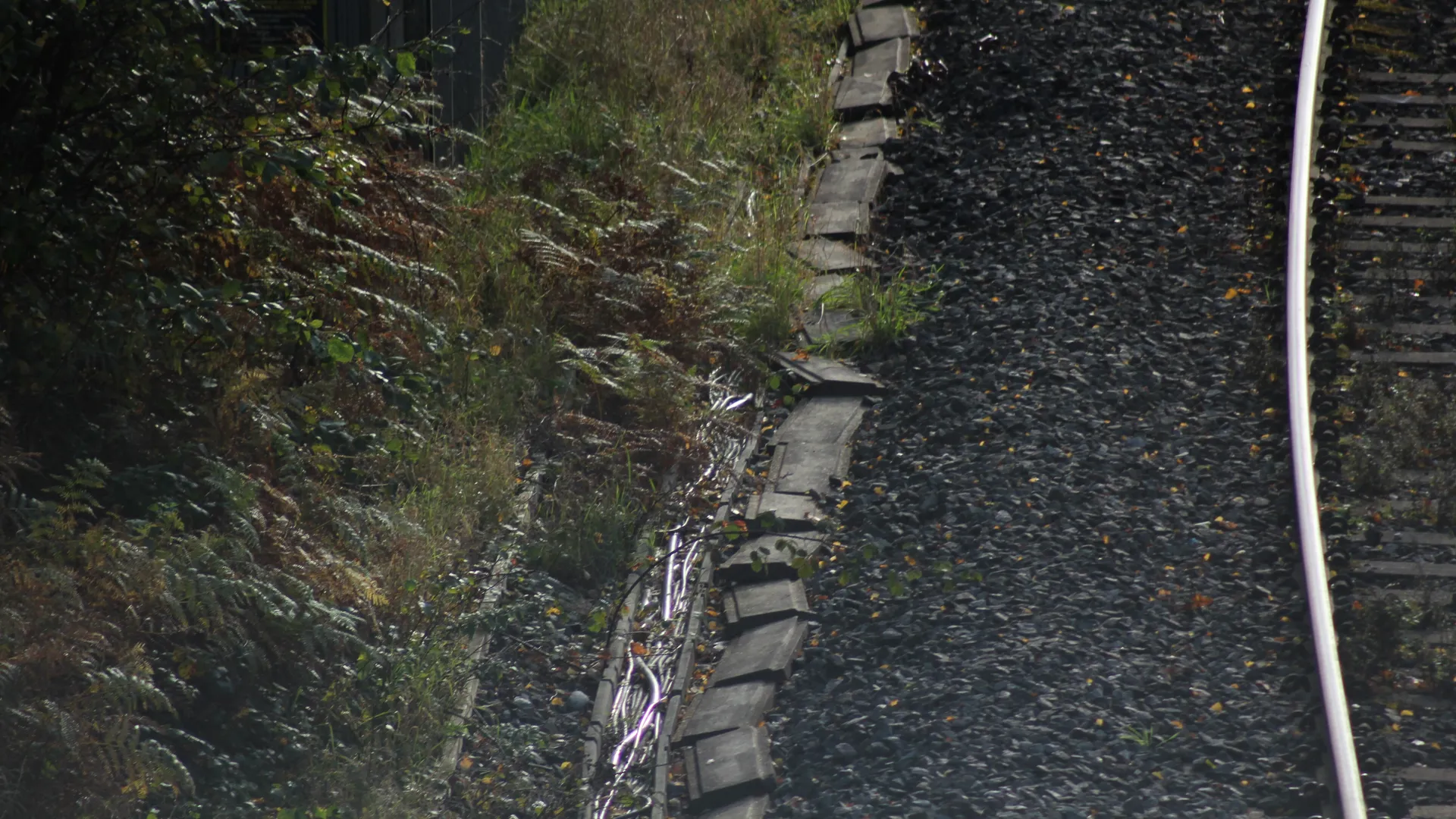
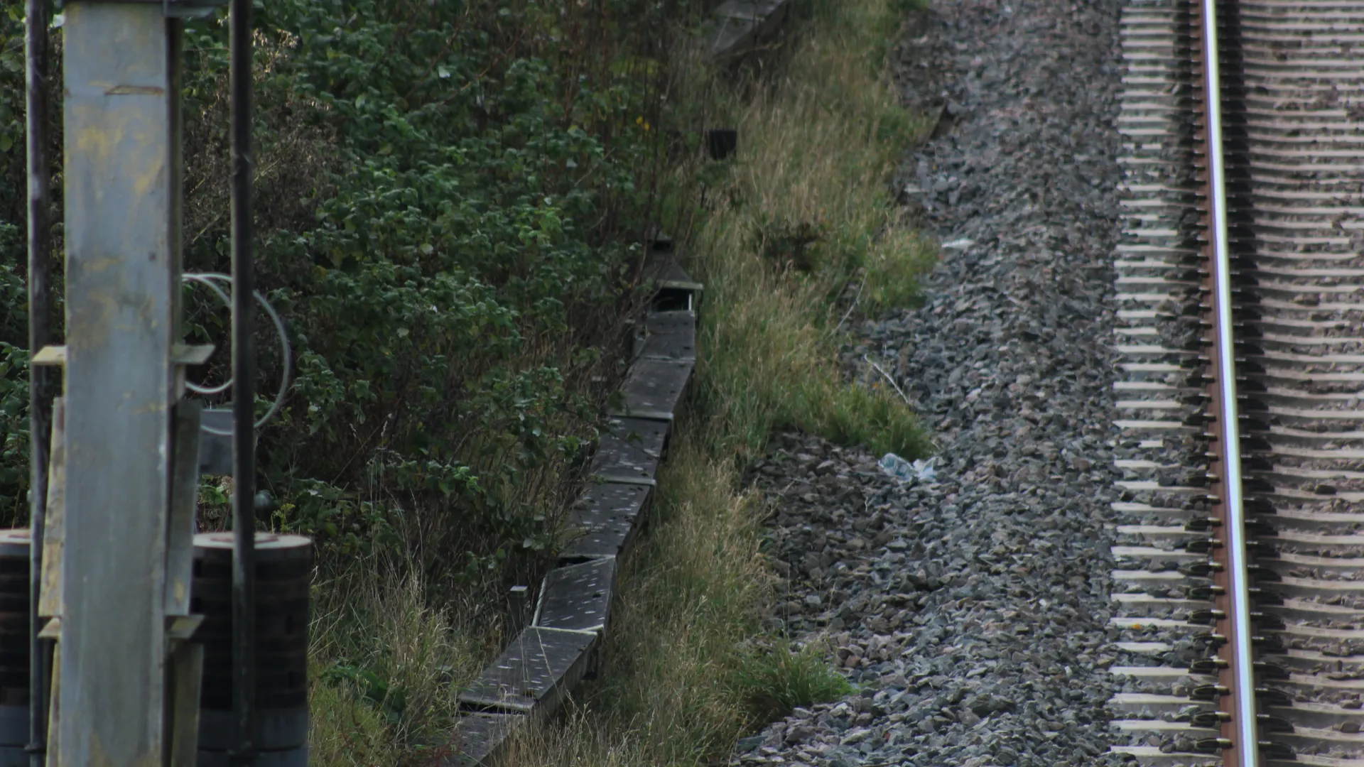
Various cables run along-side the UK railway network and include cabling required for railway signaling and fibre-optic cabling for telecommunications. These cables are housed within concrete troughs to protect them.
However, unfortunately these cables are often damaged resulting from environmental deterioration, unauthorised access, theft, or poor-quality historical repairs. Poor trough condition leaves cables vulnerable to water ingress, debris accumulation, and animal interference, leading to signalling faults, service delays, and internet outages.
Inspection of the troughs is currently conducted manually, requiring personnel to work in close proximity to live rail lines and to lift heavy troughs and lids. This necessitates having several workers for each inspection as there are handling restrictions on how many lids each worker can lift per day.
Working with valueable industrial guidance from a representative from Telent (A UK telecommunications and digital infrastrutrure company involved in the rail industry), our aim was to develop a cost-effective, remote-controlled robotic solution, to assist operators in the identification of faults within rail-side troughs.
Constraints
The project was conducted as part of a 4th year module (ES410 Group Project module) with the majority of the project occuring between October 2025 and March 2026. This corresponded to a timeline of approximately 20 weeks with academic deliverables and study also taking place concurrently. From the beginning, it was clear that we would target a low Technical Readiness Level (TRL), focussing on developing a working prototype capable of demonstrating the benefits an inspection robot would bring.
Our total allocated budget was £1642.
Troughs are available in several different sizes and shapes depending on the specific track and layout. For our project, we decided to target a C/1/9 standard trough with internal dimensions 190x130mm (WxD) as this is a common size and seemed feasibile given the project scope.
A specification focusing on 15 key points was then written, using appropriate rail industry and product standards where relevant. For instance, this defined aspects such as the targeted robot size as 100x85x150mm (WxHxL) to allow room to move inside a C/1/9 trough containing some cables/obstacles.
Design & Decisions
A range of locomotion methods were initially considered including wheeled, tracked and legged concepts. Ultimately, a tracked tank design was selected using a weighted Pugh matrix which identified its compactness and potential maneuverability whilst maintaining relative mechanical simplicity.
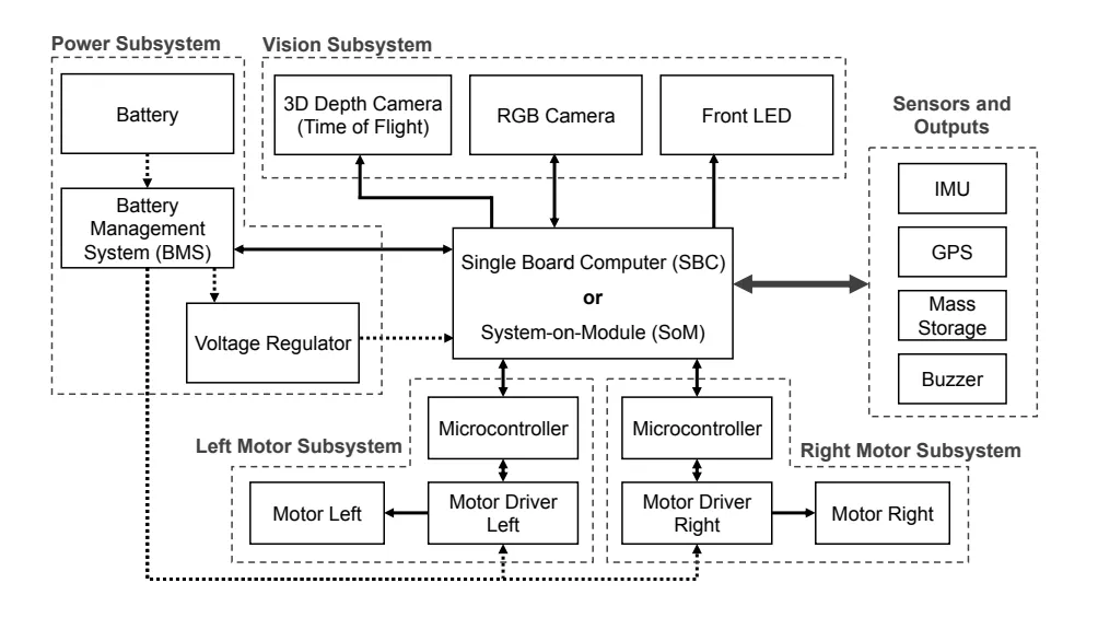
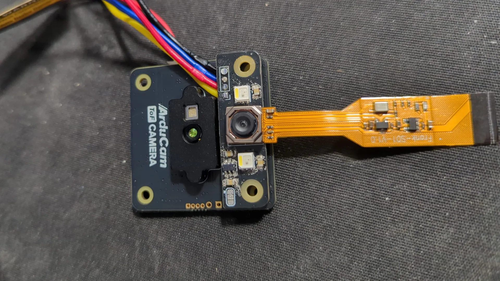
One of my personal responsibilties was to design the electical system including the required components and sensors. The block diagram here shows the inital part of this process where the overall system was planned.
Motors and Drivers
For size optimisation, using two smaller independent drive motors saved size compared to a single larger drive motor and differential system. Different motor types were considered with BLDC (Brushless DC) selected due to their torque density and size.
Calculations estimated the stall torque requirement as 0.24Nm per motor which lead selection of to CubeMars GL30 KV290 BLDC gimbal motors. These presented expectional torque density providing 0.28Nm whilst weighing only 41g each.
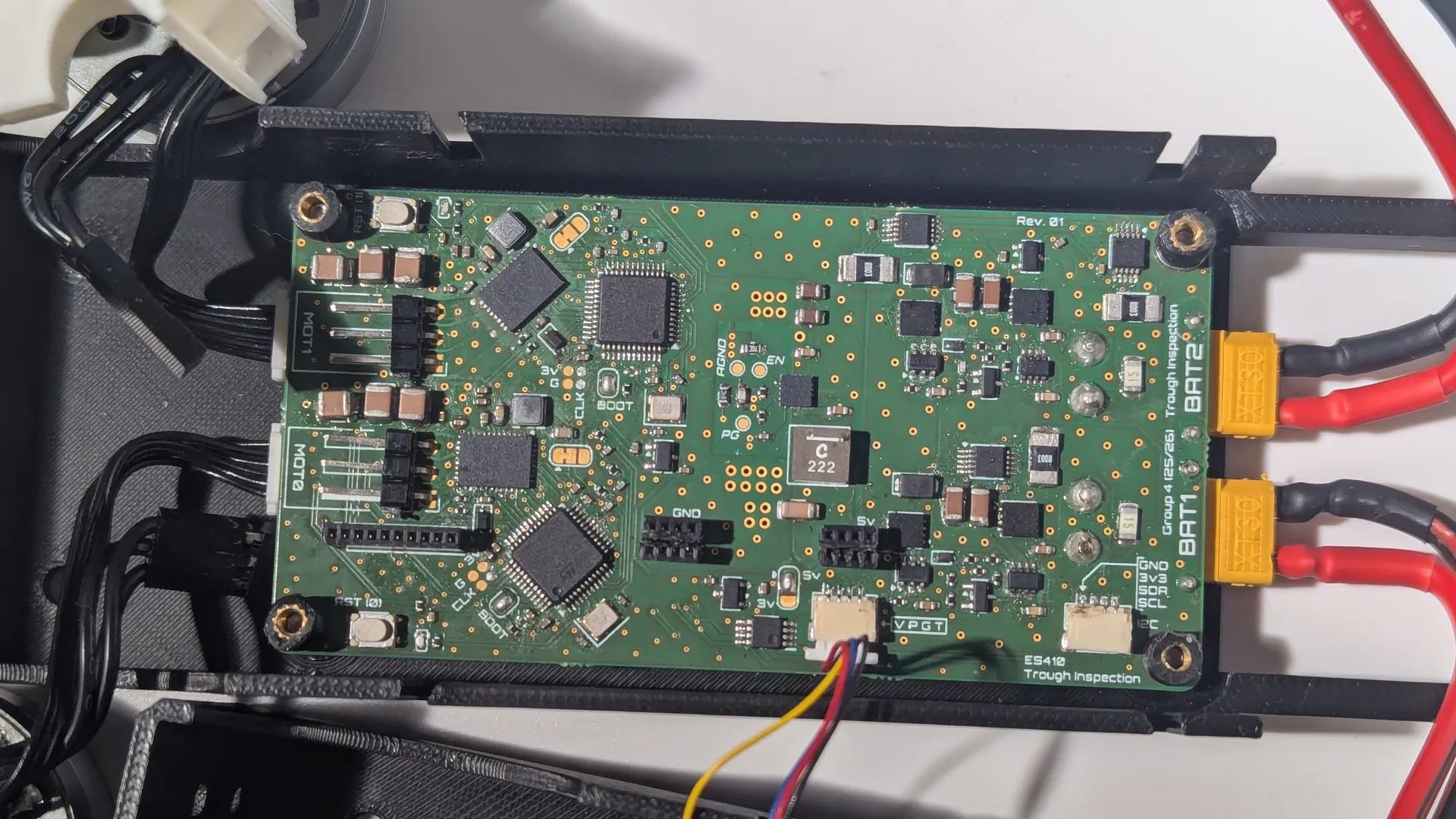
For optimal torque and efficiency, the motors are driven using Field Oriented Control (FOC), requiring positional feedback using magnetic encoders (AS5048A were chosen). I was also responsible for the motor driver circuit design which used a TI DRV8316 driver IC (packages FETs and gate drive in one which saved space) paired with a STM32G431 microcontroller.
SoM and Other Components
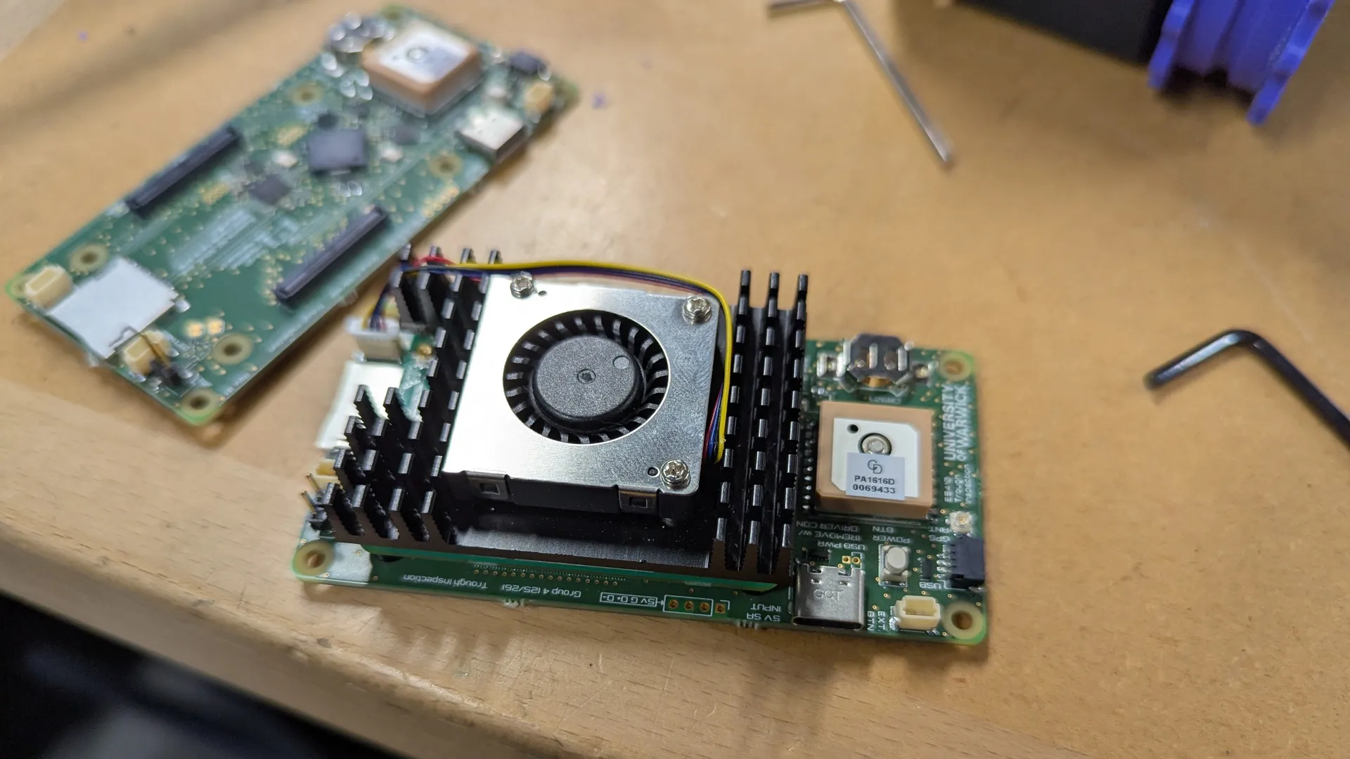
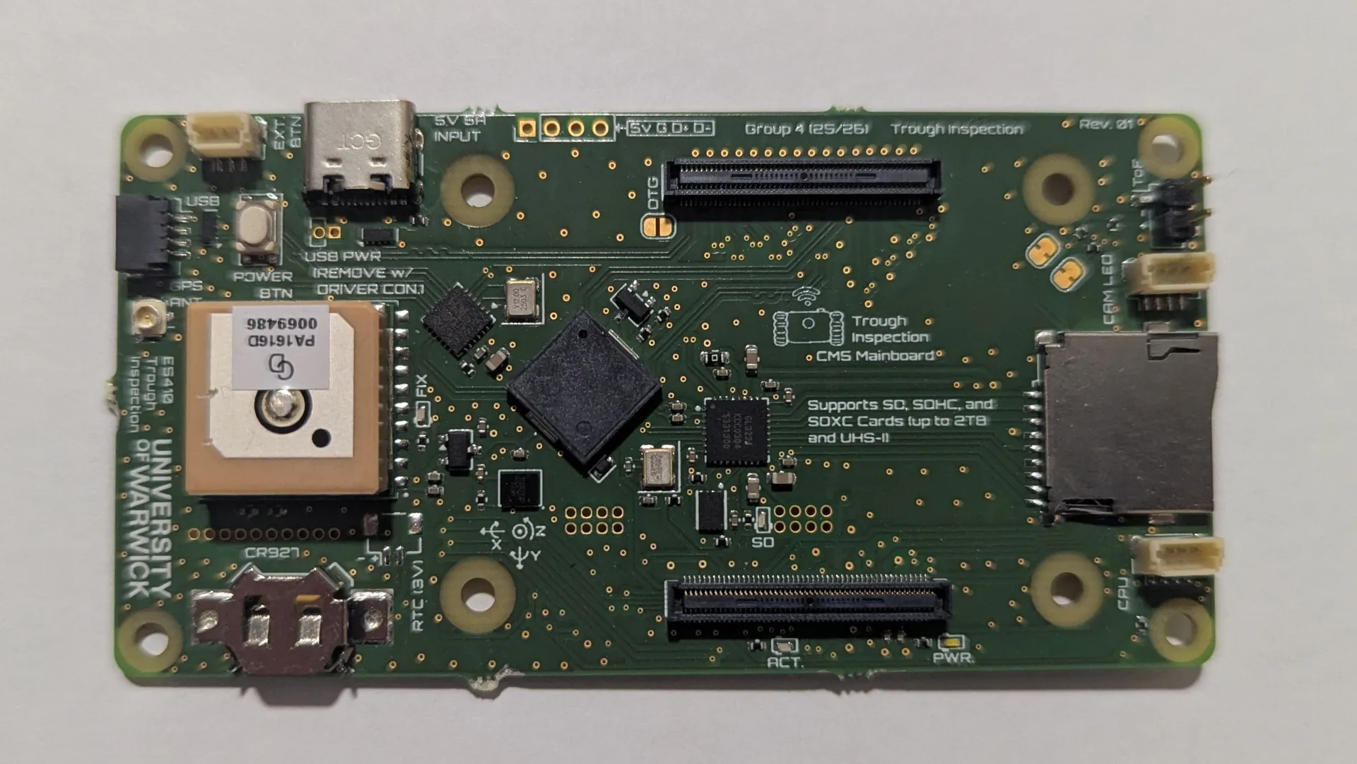
The robot uses a Raspberry Pi CM5 System-on-Module (SoM) for primary control.
- RGB Camera - Allows for visual inspection and for navigation whilst driving.
- ToF (Time of Flight) Camera - Native depth data for inspection and 3D scanning. Potential for autonomous operation.
- GPS - Low resolution positional tracking, used to log fault locations.
- IMU - Orientation and finer resolution positional tracking. Can be used for SLAM.
- SD Card Slot - Mass storage for logging and data storage.
Build
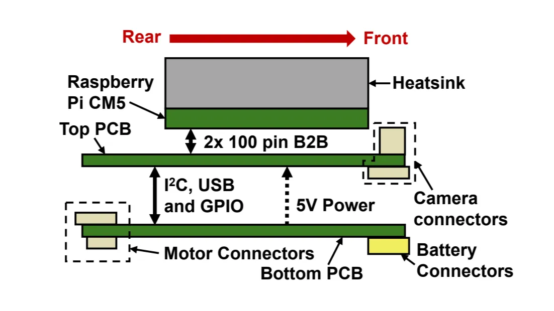
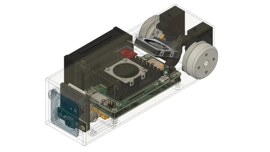
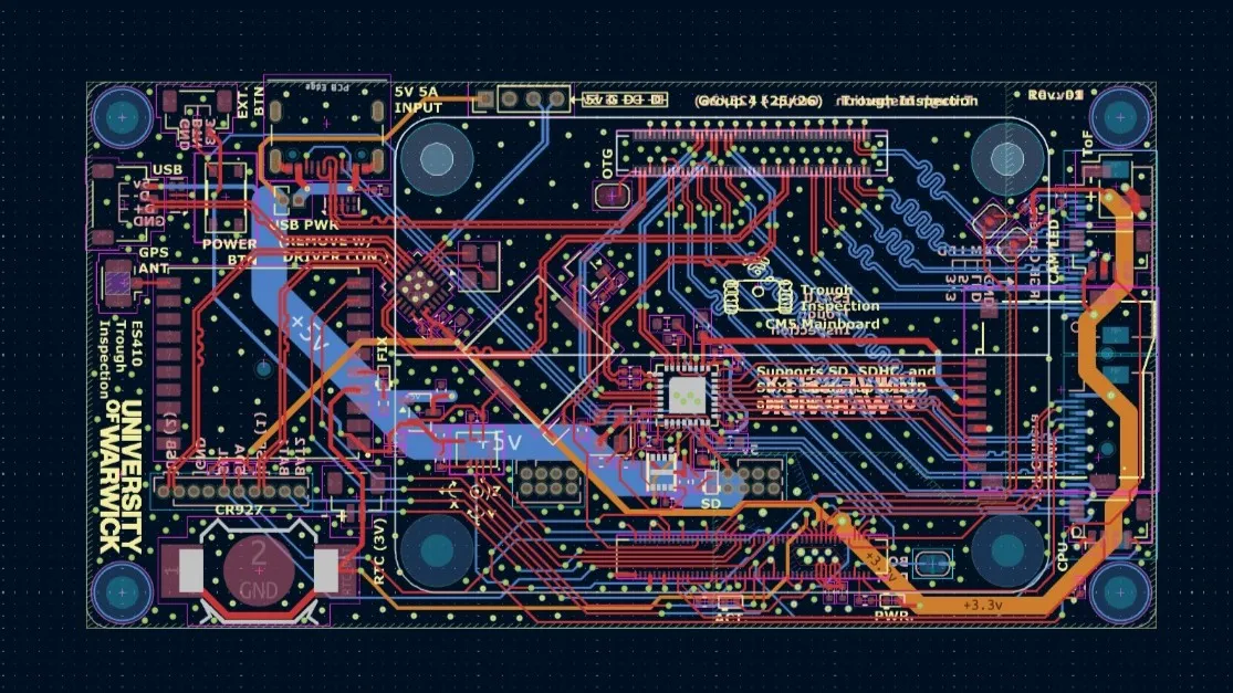
The PCB design was split into two separate vertically-stacked boards in order to make optimal use of the internal space of the robot as seen in the diagram.
The design for the PCBs are the most complex layouts I have designed up until now. I used my PCB design skills in addition to learning new techniques such as correctly length and impedence match the traces for the USB 3 and MIPI-CSI signals which was crucial for the system to function.
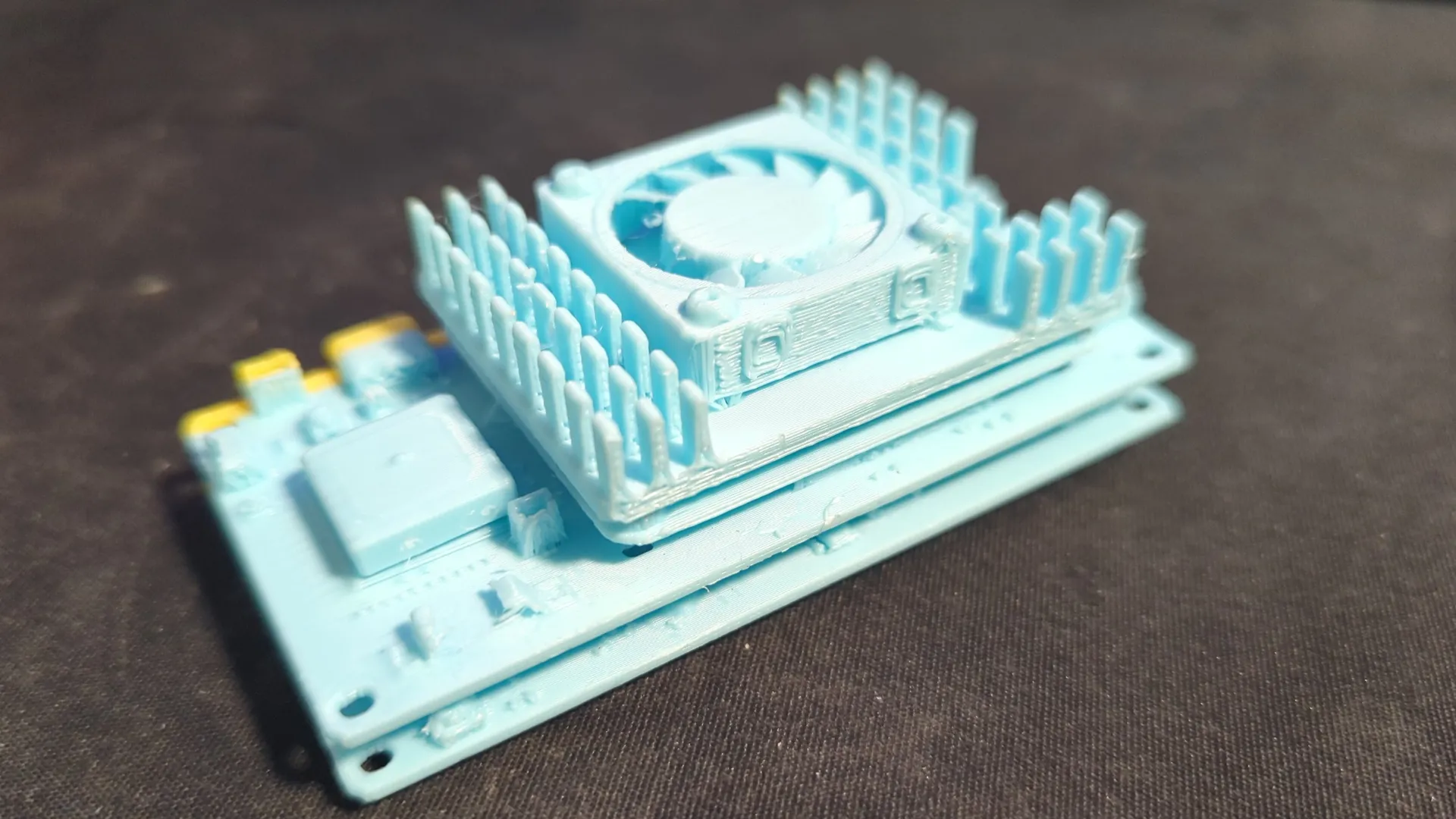
I used a 3D-printed prototype of the board for gauging the physical size to ensure it would fit inside the chassis and also for discussing with the other group members in meetings. All of the CAD for the project was done using Autodesk Fusion360.
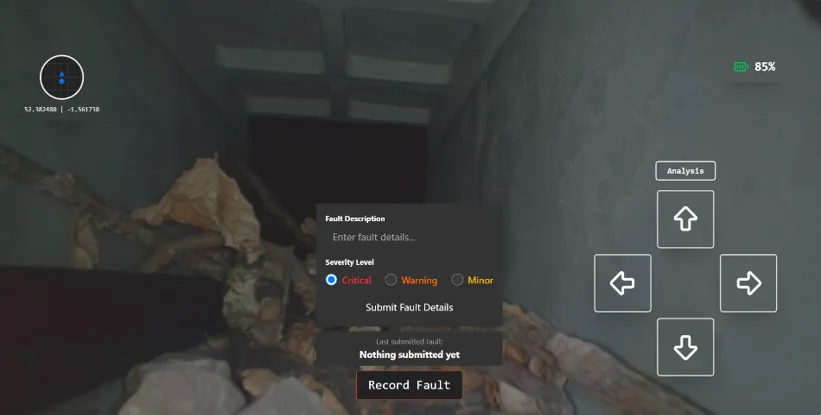
Firmware for the motor driver microcontrollers was written in C++ which communicated with the CM5 using I2C. The CM5 then ran software written in Python to command the motors as well as polling the sensors and capturing the camera streams. This was then served to a SvelteKit front-end created by one of the other electrical sub-team members.
Testing & Results
The robot was tested against the design specification, which were grouped into Manoeuvrability, Range & Endurance and Vision categories. These tests were conducted in a ‘lab’ environment which is appropriate to our TRL. Higher TRLs would require entail testing in a representative environment such as one of Network Rail’s Test Tracks. This is subject to regulatory requirements and lots of paperwork!
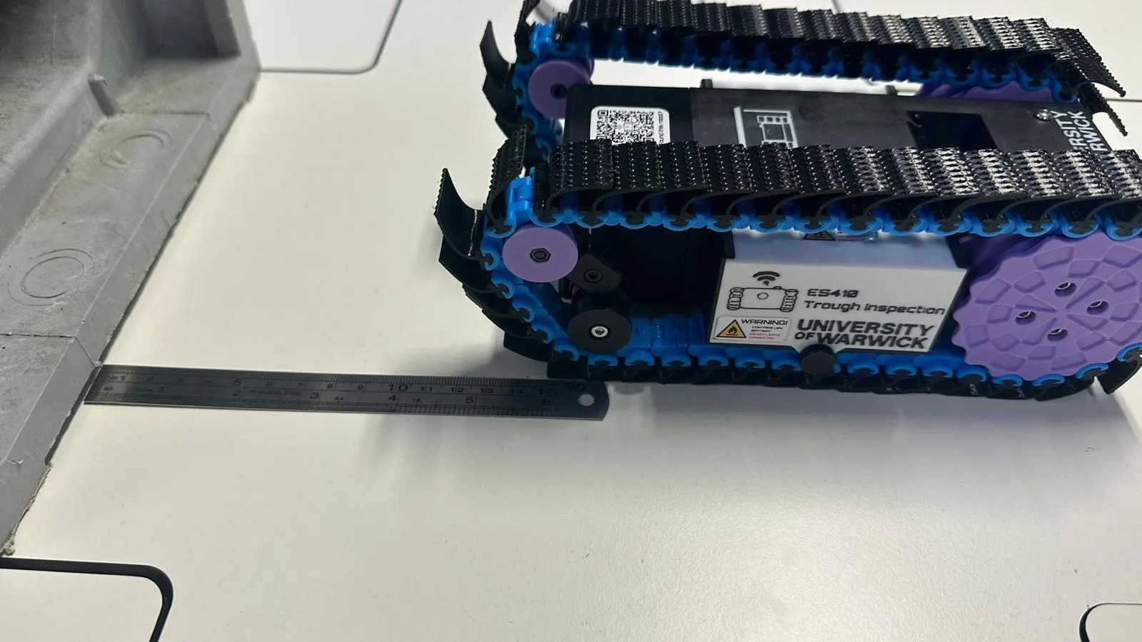
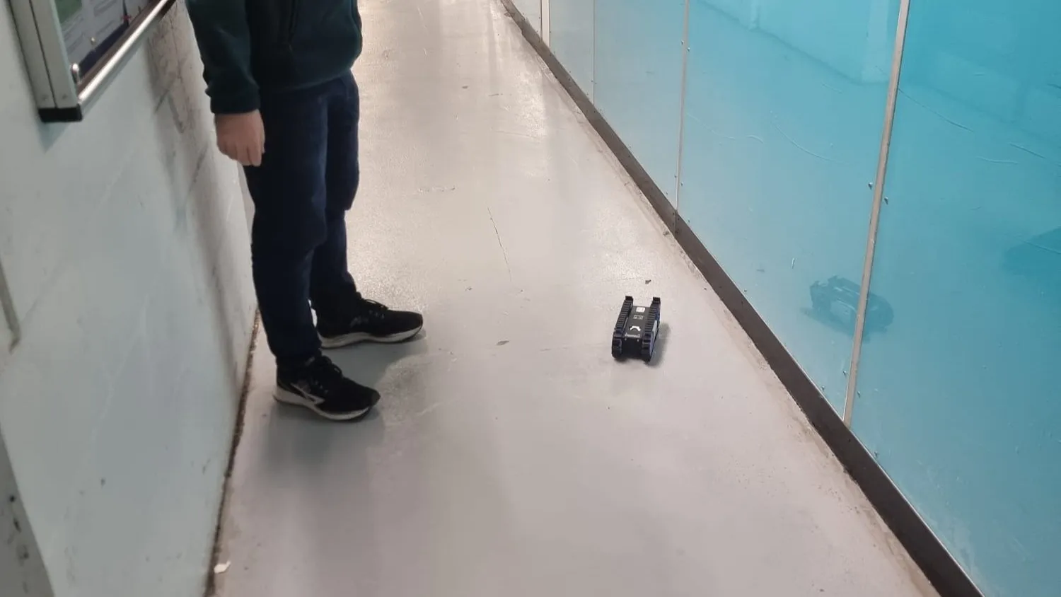
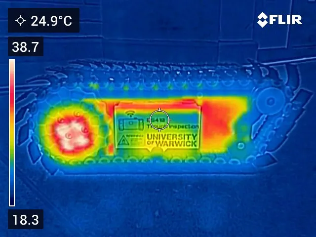
Manoeuvrability
- A Vertical step
- A Trough misalignment
- Random uneven terrain
- A 90° T-junction turn
These tests were conducted with 3 repeats each and the robot passed every test.
Range & Endurance
- Wireless range from operator
- Distance travelled on one battery
- Time taken for battery swap
The robot achieved a mean 30.7m in the wireless range test however this was in a non-representive environment with stock antennas (greater range would be possible but would require RF power testing for regulatory requirements). Consecutive 5m runs yielded 525m endurance on half capacity, corresponding to 21 minutes of runtime. Changing both batteries took approximately 24 seconds.
Vision
- Ability to operate in low-light
- Clearness of video feed
- Assessment of ToF camera data
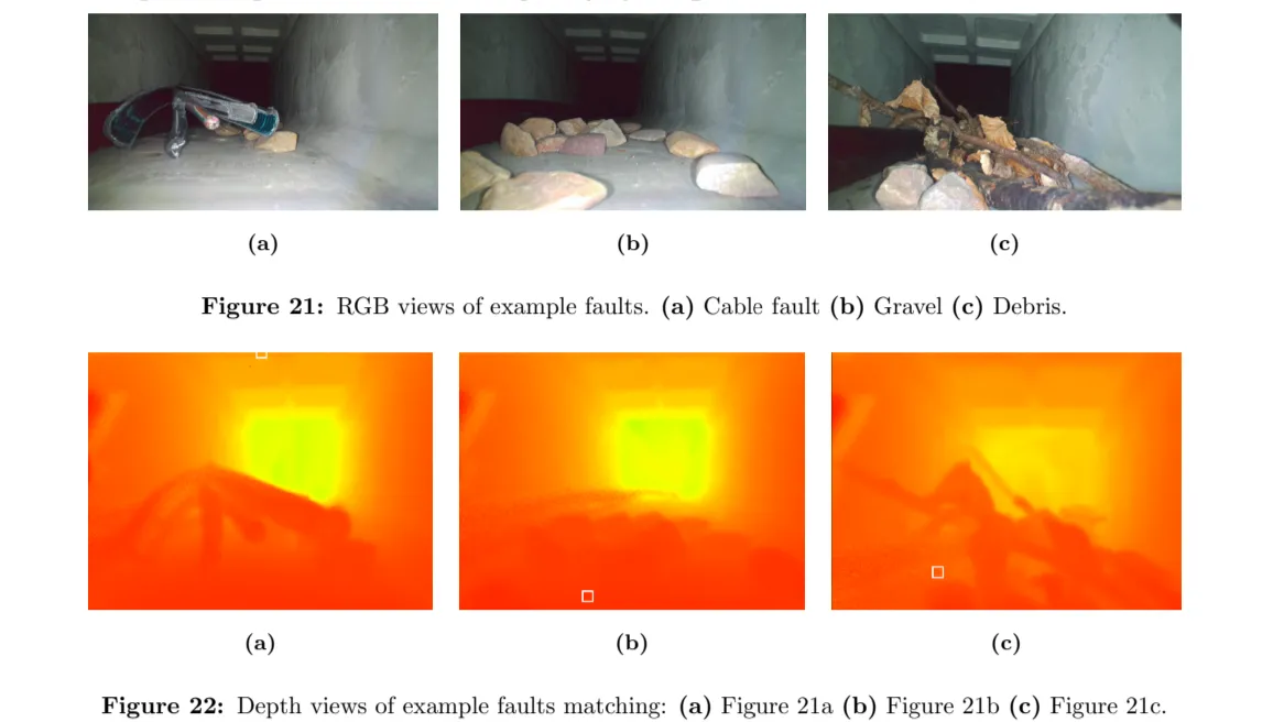
As seen in the image, the RGB camera images are high resolution and suitable for visual inspection. The depth maps from the ToF camera shows useful data obtained.
Design Analysis
Several issues arised during testing and general useage of the robot. There was sufficient control to navigate turns however low-speed navigation was difficult. This could we solved by a more complex control algorithm for controlling the tracks such as using data from the IMU data to better managed the differential torque between the two tracks.
Durability was also a concern with the sprocket bolts becoming loose over long distances. This was likely caused by vibration in addition to heat from the motors softening the 3D-printed PLA sprockets. This can be solved by using a different material with higher glass transition temperature.
Reflecting on the Project
I learnt and developed a lot of skills throughout the course of this project, especially in time management, communication and leadership. Being the leader of the electrical sub-team highlighted how important effective communication is and how to manage time and efficiency delagate tasks between the members.
The project was very time constrained with many ‘distracting’ factors including coursework and exams due during the project timeline. I feel that I was able to improve this during the progression of the project and was able to manage my time more efficiently by the end.
Overall, I am satisfied and proud of what I was able to achieve in this project and through working as a team we were able to successfully meet the objectives and make something to further the technology and move closer to creating a useful product.